

『Flow Meter Check Valve Placement: Preventing Backflow Inaccuracies and Sensor Damage』Related information(v cone flow meter|rotary gas meter|gallon meter|gear meter|metal tube rotameter|glass tube rotameter|nutating disk meter|transit time ultrasonic flow meter|wedge flow meter|pd meters|hydraulic flow meter|ultrasonic water flow meter|water flow meter|air flow meter|magnetic water flow meter|oxygen flow meter|gas flow meter|argon flow meter|air velocity meter|gasoline flow meter|fuel flow meter|ultrasonic water meter|digital water meter|nitrogen flow meter|solid flow meter|Oxygen tank flow meter|digital water flow meter|diesel fuel flow meter|steam flow meter|02 flow meter|compressed air flow meter|oil flow meter|liquid flow meter)
Flow Meter Check Valve Placement: Preventing Backflow Inaccuracies and Sensor Damage
Quick Answer: Install the check valve downstream of the flow meter, not upstream. Keep 5 to 10 DN of straight pipe between the meter and the check valve where possible. This prevents reverse flow, water hammer, and sensor strain that cause incorrect readings and early failure.
Why Check Valve Position Affects Flow Meter Accuracy
Flow meter check valve placement is a small layout decision with a large effect on measurement. Many installation drawings leave it to the pipe fitter. That creates avoidable errors.
Here is the thing. A check valve is not a flow conditioner. It is a mechanical device that opens and closes. When installed upstream of a meter, the flapper or spring disc changes the flow profile before the sensor can read it.
Most flow meters assume a stable velocity profile. A check valve opening and closing upstream of the meter disturbs that profile. The disc or ball inside the check valve creates swirl and asymmetric flow. This is worse on short straight runs.
We saw this at a desalination plant in Saudi Arabia. The site read 6 percent high after installing a check valve only 3 DN before a DN150 electromagnetic flow meter. The plant moved the valve to the downstream side. The reading returned to normal within one day.
Correct Placement for Common Meter Types
For electromagnetic flow meters, mount the check valve after the sensor. Keep the meter tube full at all times. A downstream check valve holds liquid in the pipe during pump stops. For DN15 to DN300 lines, 5 DN of straight pipe after the meter is a practical minimum. Some projects use 10 DN.
For Coriolis mass flow meters, reverse flow does not always damage the tubes right away. But repeated reverse flow can shift the zero and cause kg/h errors. Install the check valve downstream. If the fluid can flash or contain gas, put a back pressure valve downstream as well.
For ultrasonic and vortex meters, upstream check valves create a bad velocity profile. This is even worse with clamp-on ultrasonic meters. Downstream placement keeps the transducer signal clean.
For oval gear flow meters, backflow can force the gears to rotate in reverse. This can damage the gear set or the pulse pickup. A check valve after the meter is mandatory on diesel and fuel oil lines.
Common Mistakes We See on Customer Sites
One mistake is placing the check valve directly at the meter inlet. This saves space but causes unstable readings on DN50 and smaller pipes. The valve disc flutters at low flow and the meter sees noise. We saw this on a paint batching line in Vietnam. The operator complained that the batch total would not repeat. Moving the check valve to the outlet solved the problem.
Another mistake is ignoring water hammer. A check valve that slams shut downstream of a meter can send a pressure wave back through the sensor. Coriolis meters with thin tubes and oval gear meters with tight clearances suffer the most. Add a soft close check valve or a small air vessel downstream if the line pressure exceeds 10 bar or if the pump stops suddenly.
Some engineers install two check valves, one before and one after. This looks safe but traps pressure between the valves during thermal expansion. The sensor sees pressure spikes above its rating. Use one check valve downstream unless the process demands a second back pressure valve with a relief path.
Sensor Damage from Backflow and How to Prevent It
Backflow
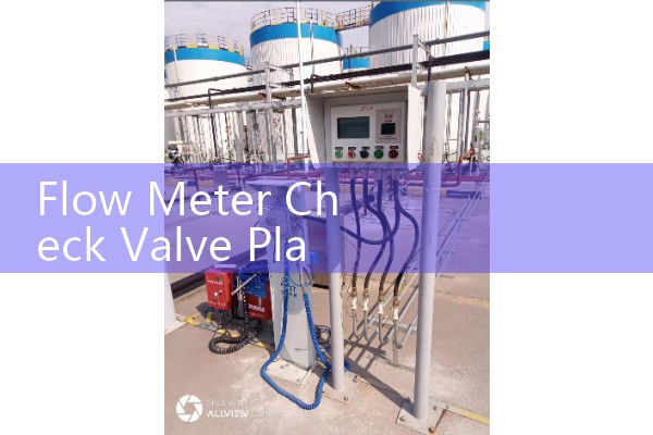
The fix is simple. Put the check valve downstream. Keep the meter full. Use straight runs before the meter, 5 DN minimum for most meters and 10 DN for vortex types. Use a flow conditioner if the pipe layout is tight. And do not mount the check valve close to the meter outlet on high velocity lines. The disc movement can be transferred directly into the meter body.
Recommended Silver Instruments Models
Silver Automation Instruments supplies meters that work well with correct check valve placement. For water and wastewater, the electromagnetic flow meter series covers DN10 to DN2000 with 4-20 mA HART, RS485, and optional ATEX Zone 1 for hazardous areas. The meter works on clean water, wastewater, and chemicals above 5 µS/cm.
For chemical and fuel oil, the Coriolis mass flow meter measures kg/h, density, and temperature in one unit. For desalination and large seawater lines, the ultrasonic flow meter handles high flow rates without cutting the pipe. For diesel, furnace oil, and viscous fluids up to 2000 cP, the oval gear flow meter gives repeatable batch totals. For steam and gas, the vortex flow meter works with a PT100 temperature input and a pressure transmitter for compensated flow.
Silver Automation Instruments also supplies pressure transmitters and paperless recorders. A pressure transmitter installed near the check valve can log pressure spikes and help you adjust the valve closing speed.
Send us your pipe size (DN), flow range (m3/h or kg/h), pressure (bar), temperature (°C), and fluid name. We will suggest a meter model and check valve position for your line. Tel: +86-25-68650347. Whatsapp: +86-25-52155837. WeChat: +86 15365082610.
FAQ: Flow Meter Check Valve Placement
Q: Should the check valve be before or after the flow meter?
A: After the flow meter. This keeps the meter full, prevents reverse flow, and avoids disturbing the velocity profile right before the sensor.
Q: How many straight pipe diameters do we need between the meter and the check valve?
A: Use 5 DN minimum after the meter. Use 10 DN if the valve is a swing check valve or the line velocity is above 3 m/s.
Q: Can a check valve damage a Coriolis flow meter?
A: Not by itself. A downstream check valve that slams shut can send a pressure wave backward. Over time this shifts the zero and may damage thin tubes. Use a soft close check valve on high pressure lines.
Q: What is the best placement for a check valve with a magnetic flow meter?
A: Downstream of the sensor. Keep the meter tube full and avoid negative pressure. This protects the liner and keeps readings stable.
Q: Do we need two check valves on a fuel oil flow meter line?
A: Normally no. One check valve downstream is enough. Two can trap pressure between them. If you need back pressure, add a separate back pressure valve with a relief path.
We have helped plants in Malaysia, Vietnam, Saudi Arabia, Chile, and Nigeria with check valve placement on fuel, water, chemical, and seawater lines. Tell us your fluid and line data. We reply with a meter quote and a simple installation sketch.
 Hot Blog
 Related AD